Tuesday, December 11, 2012

Back In Time Final

Materials Needed:
 -1 battery

-1 SD card

-14 Jumper Wires


-4 330 Ohm Resistors

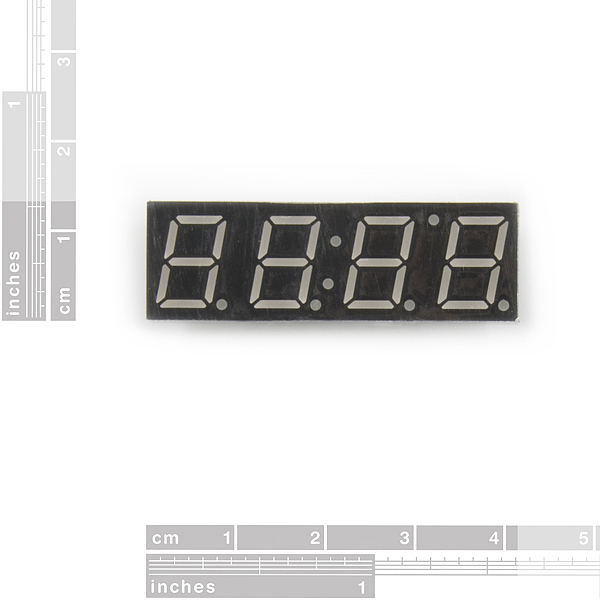
-7-Segment Display
1
7-Segment Display Pin 1 to Pin 8 counted from left to right on the bottom of the display.  From Pin 9 to 16 counted from right to left on the top of the display.

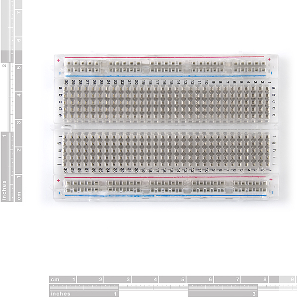
-Breadboard

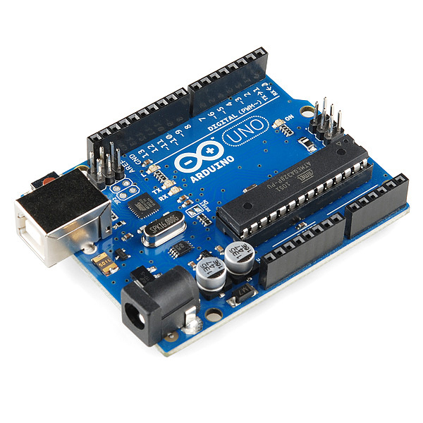
-Arduino Uno
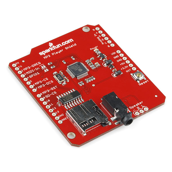
-Mp3 Shield


- two 6 Pin Headers 
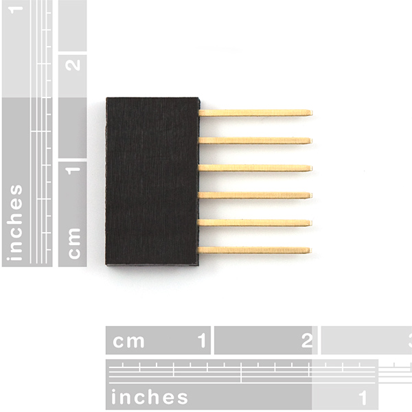


-two 8 Pin Headers

Breadboard Organization (A-J/ 1-30) & Arduino Uno (Digital 1-11)

7-Segment Display on Breadboard
Pin 1 on E9
Pin 2 on E10
Pin 3 on E11
Pin 4 on E12
Pin 5 on E13
Pin 6 on E14
Pin 7 on E15
Pin 8 on E16
Pin 9 on G16
Pin 10 on G15
Pin 11 on G14
Pin 12 on G13
Pin 13 on G12
Pin 14 on G11
Pin 15 on G10
Pin 16 on G9

Connecting Breadboard to the MP3 Shield
A1 connected with a 330 Ohm Resistor on D1 to Pin 1 (D9)
A1 connected to Digital 12
A2 connected with a 330 Ohm Resistor on C2 to Pin 2 (D10)
A2 connected to Digital 11
A11 connected to Digital 4 for Pin 3
No connection for Pin 4
A13 connected to Digital 5 for Pin 5
A22 connected with a 330 Ohm Resistor on C22 to Pin 6 (C14)
A22 connect to Digital 10
A15 connected to Digital 8 for Pin 7
A23 connected with a 330 Ohm Resistor on D23 to Pin 8 
A23 connected to Digital 9 for Pin 8

No connection for Pin 9
No connection for Pin 10
J14 connected to Digital 6 for Pin 11
No connection for Pin 12
J12 connected to Digital 3 for Pin 13
J11 connected to Digital 1 for Pin 14
J10 connected to Digital 7 for Pin 15
J9 connected to Digital 2

Switch connector to Power 5V and Analog A5

For the Mp3 Shield:
Solder the two 6 pin headers and the two 8 pin headers into the Mp3 shield.
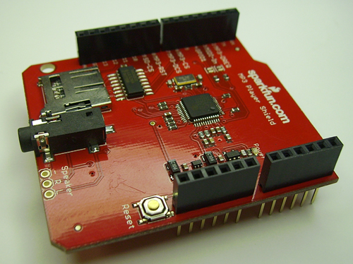

Attach the MP3 shield on top of the arduino uno. Note: make sure the USB socket has electric tape around it to avoid short circuiting the MP3 Shield.


How to program the MP3 Shield:

Read the Quickstart Tutorial: http://www.sparkfun.com/tutorials/295

Download and Unzip the sdfatlib folder and inside this folder it will contain a folder named SDfat. If you are using a Mac open your applications folder and right click on the Arduino App Icon and go to expand contents. Look for the libraries folder and then drag the sdfat folder, found in the sdfatlib folder, into the libraries folder. If you have the Arduino Application open you must close it and reopen it so the SDfat folder will appear under file --> examples.

To program the MP3 shield first you find the song you want to play with the MP3 shield and you put in the SD card and you rename it track001.mp3 and not just track1.mp3, because it will not play. Then insert the SD card into the MP3 Shield.

The code for the MP3 shield:

#include <SPI.h>
#include <SdFat.h>
#include <SdFatUtil.h>
#include <SFEMP3Shield.h>

SFEMP3Shield MP3player;

void setup() {

  Serial.begin(9600);

  //start the shield
  MP3player.begin();

  //start playing track 1
  MP3player.playTrack(1);
}

//do something else now
void loop() {

  Serial.println("I'm bored!");
  delay(2000);

}

The code for the 7-segment display with random effects:

//segments
int a = 1;
int b = 2;
int c = 3;
int d = 4;
int e = 5;
int f = 6;
int g = 7;
int p = 8;
//digits
int d4 = 9;
int d3 = 10;
int d2 = 11;
int d1 = 12;
//other
int del = 100;
int buttoncount = 0;
int loopcount = 0;

void setup()
{
  pinMode(d1, OUTPUT);
  pinMode(d2, OUTPUT);
  pinMode(d3, OUTPUT);
  pinMode(d4, OUTPUT);
  pinMode(a, OUTPUT);
  pinMode(b, OUTPUT);
  pinMode(c, OUTPUT);
  pinMode(d, OUTPUT);
  pinMode(e, OUTPUT);
  pinMode(f, OUTPUT);
  pinMode(g, OUTPUT);
  pinMode(p, OUTPUT);
  digitalWrite(a, HIGH);
  digitalWrite(b, HIGH);
  digitalWrite(c, HIGH);
  digitalWrite(d, HIGH);
  digitalWrite(e, HIGH);
  digitalWrite(f, HIGH);
  digitalWrite(g, HIGH);
  digitalWrite(p, HIGH);
}

void loop()
{
  roulette(4);
  delay(100);
  zigzag(2);
  delay(100);
  circles(4);
  delay(100);
}

void pickDigit(int x)
{
  digitalWrite(d1, LOW);
  digitalWrite(d2, LOW);
  digitalWrite(d3, LOW);
  digitalWrite(d4, LOW);

  switch(x)
  {
  case 1: 
    digitalWrite(d1, HIGH); 
    break;
  case 2: 
    digitalWrite(d2, HIGH); 
    break;
  case 3: 
    digitalWrite(d3, HIGH); 
    break;
  default: 
    digitalWrite(d4, HIGH); 
    break;
  }
}

void clearLEDs()
{
  digitalWrite(a, HIGH);
  digitalWrite(b, HIGH);
  digitalWrite(c, HIGH);
  digitalWrite(d, HIGH);
  digitalWrite(e, HIGH);
  digitalWrite(f, HIGH);
  digitalWrite(g, HIGH);
  digitalWrite(p, HIGH);
}

void roulette(int x)
{
  loopcount = 0;
  while (loopcount < x)
  {
    digitalWrite(a, LOW);
    pickDigit(1);
    delay(del);
    pickDigit(2);
    delay(del);
    pickDigit(3);
    delay(del);
    pickDigit(4);
    delay(del);
    digitalWrite(a, HIGH);
    digitalWrite(b, LOW);
    delay(del);
    digitalWrite(b, HIGH);
    digitalWrite(c, LOW);
    delay(del);
    digitalWrite(c, HIGH);
    digitalWrite(d, LOW);
    delay(del);
    pickDigit(3);
    delay(del);
    pickDigit(2);
    delay(del);
    pickDigit(1);
    delay(del);
    digitalWrite(d, HIGH);
    digitalWrite(e, LOW);
    delay(del);
    digitalWrite(e, HIGH);
    digitalWrite(f, LOW);
    delay(del);
    clearLEDs();
    loopcount++;
  }
}

void zigzag(int x)
{
  loopcount = 0;
  while(loopcount < x)
  {
    digitalWrite(a, LOW);
    pickDigit(1);
    delay(del);
    pickDigit(2);
    delay(del);
    pickDigit(3);
    delay(del);
    pickDigit(4);
    delay(del);
    digitalWrite(a, HIGH);
    digitalWrite(b, LOW);
    delay(del);
    digitalWrite(b, HIGH);
    digitalWrite(g, LOW);
    delay(del);
    pickDigit(3);
    delay(del);
    pickDigit(2);
    delay(del);
    pickDigit(1);
    delay(del);
    digitalWrite(g, HIGH);
    digitalWrite(e, LOW);
    delay(del);
    digitalWrite(e, HIGH);
    digitalWrite(d, LOW);
    delay(del);
    pickDigit(2);
    delay(del);
    pickDigit(3);
    delay(del);
    pickDigit(4);
    delay(del);
    digitalWrite(d, HIGH);
    digitalWrite(c, LOW);
    delay(del);
    digitalWrite(c, HIGH);
    digitalWrite(g, LOW);
    delay(del);
    pickDigit(3);
    delay(del);
    pickDigit(2);
    delay(del);
    pickDigit(1);
    delay(del);
    digitalWrite(g, HIGH);
    digitalWrite(f, LOW);
    delay(del);
    clearLEDs();
    loopcount++;
  }
}

void circles(int x)
{
  loopcount = 0;
  while (loopcount < x)
  {
    digitalWrite(a, LOW);
    digitalWrite(b, LOW);
    digitalWrite(f, LOW);
    digitalWrite(g, LOW);
    pickDigit(1);
    delay(250);
    digitalWrite(a, HIGH);
    digitalWrite(b, HIGH);
    digitalWrite(f, HIGH);
    digitalWrite(c, LOW);
    digitalWrite(d, LOW);
    digitalWrite(e, LOW);
    pickDigit(2);
    delay(250);
    digitalWrite(a, LOW);
    digitalWrite(b, LOW);
    digitalWrite(f, LOW);
    digitalWrite(c, HIGH);
    digitalWrite(d, HIGH);
    digitalWrite(e, HIGH);
    pickDigit(3);
    delay(250);
    digitalWrite(a, HIGH);
    digitalWrite(b, HIGH);
    digitalWrite(f, HIGH);
    digitalWrite(c, LOW);
    digitalWrite(d, LOW);
    digitalWrite(e, LOW);
    pickDigit(4);
    delay(250);
    clearLEDs();
    loopcount++;
  }
} 


Artist Statement
 
 
The name of this project is called Back In Time, which plays and explores the concept
of music and time. Music is unlimited and continues in time, but a song is limited 
to a specific time in that there is so much a song can be played in a certain
time frame. Time is also set with a limit that it can go up to as well as time
keeps going up and can never be completely stopped. This project looks at time as 
can be manipulated to not read the right time or cause random effects with the time 
display as if to say that time is never set and can be changed into anything that a 
person could think of time as. Though the song being played with the time is a song 
by Pitbull called Back In Time which brings the concept of music and time together 
in that both can be manipulated to mean anything and to change it to be anything 
anybody wants it to be in the realm of science fiction and imagination. There is 
always a want for the music to keep going as well as for time to stop, skip, move 
forward, play back, and reverse. Just as time is this music is as well that it can
be stopped, skipped, moved forward, played back, and reversed. It is the ability 
that we have to connect time to music and feel that we can manipulate time through 
music. This project demonstrates the artistic concept of music and time as well as
the technology capable of manipulating both these concepts. 
 
In Project Progress
 
This project was a bit difficult because it was the first time I have ever played with a shield for the arduino. As 
well as learning how to program the MP3 shield so that it works. After reading so many other blogs and websites 
about programming the MP3 shield, it first made me frustrated and confused since I was doing everything
as instructed so I asked for help from the professor because I remembered that she introduced the MP3 shield 
to class and I knew that she might no more about programming it. I was right about the professor and helped me
a lot figure what I was doing wrong and can say that blogs and websites are not always that descriptive and step 
by step instructions. I also had a rough time figuring out the code for the MP3 shield, but after looking at websites
I found the easiest and simple code to play and work for the MP3 shield. There was one problem that I have left 
as is which is the combining of both the MP3 shield code and the 7-segment display code which I try my best to 
understand and reword the program so that both codes work together, but unfortunately I haven't found the  
solution yet and try to rely on blogs and websites for help.        
 

Tuesday, November 6, 2012

Midterm Project In Time

Materials Needed:
 -1 battery

-1 switch

-14 Jumper Wires


-4 330 Ohm Resistors

-7-Segment Display
1
7-Segment Display Pin 1 to Pin 8 counted from left to right on the bottom of the display.  From Pin 9 to 16 counted from right to left on the top of the display.

-Breadboard


-Arduino Uno

Breadboard Organization (A-J/ 1-30) & Arduino Uno (Digital 1-11)

7-Segment Display on Breadboard
Pin 1 on E9
Pin 2 on E10
Pin 3 on E11
Pin 4 on E12
Pin 5 on E13
Pin 6 on E14
Pin 7 on E15
Pin 8 on E16
Pin 9 on G16
Pin 10 on G15
Pin 11 on G14
Pin 12 on G13
Pin 13 on G12
Pin 14 on G11
Pin 15 on G10
Pin 16 on G9

Connecting Breadboard to Arduino Uno
A1 connected with a 330 Ohm Resistor on D1 to Pin 1 (D9)
A1 connected to Digital 12
A2 connected with a 330 Ohm Resistor on C2 to Pin 2 (D10)
A2 connected to Digital 11
A11 connected to Digital 4 for Pin 3
No connection for Pin 4
A13 connected to Digital 5 for Pin 5
A22 connected with a 330 Ohm Resistor on C22 to Pin 6 (C14)
A22 connect to Digital 10
A15 connected to Digital 8 for Pin 7
A23 connected with a 330 Ohm Resistor on D23 to Pin 8 
A23 connected to Digital 9 for Pin 8

No connection for Pin 9
No connection for Pin 10
J14 connected to Digital 6 for Pin 11
No connection for Pin 12
J12 connected to Digital 3 for Pin 13
J11 connected to Digital 1 for Pin 14
J10 connected to Digital 7 for Pin 15
J9 connected to Digital 2

Switch connector to Power 5V and Analog A5


Code:
//This code was copied from http://www.instructables.com/id/4-Digit-7-Segment-LED-Display-Arduino/?ALLSTEPS, but this code was rewritten and fixed because the original code was not working for my project as well as added a swtich program code into this code.
//This project reflects the idea of time as an artistic concept in which time is what the world runs on and even though society or individuals wishes to stop time, time continues going on.


//segments
int a = 1;
int b = 2;
int c = 3;
int d = 4;
int e = 5;
int f = 6;
int g = 7;
int p = 8;
//digits
int d4 = 9;
int d3 = 10;
int d2 = 11;
int d1 = 12;
//other
long n = 0;
int x = 100;
int del = 45;
int switch1;

void setup()
{
  pinMode(d1, OUTPUT);
  pinMode(d2, OUTPUT);
  pinMode(d3, OUTPUT);
  pinMode(d4, OUTPUT);
  pinMode(a, OUTPUT);
  pinMode(b, OUTPUT);
  pinMode(c, OUTPUT);
  pinMode(d, OUTPUT);
  pinMode(e, OUTPUT);
  pinMode(f, OUTPUT);
  pinMode(g, OUTPUT);
  pinMode(p, OUTPUT);
  pinMode(A5, INPUT);
}

void loop()
{
  switch1 = digitalRead(A5);
  if (switch1 == LOW) {
  clearLEDs();
  pickDigit(1);
  pickNumber((n/x/1000)%10);
  delayMicroseconds(del);
 
  clearLEDs();
  pickDigit(2);
  pickNumber((n/x/100)%10);
  delayMicroseconds(del);
 
  clearLEDs();
  pickDigit(3);
  dispDec(3);
  pickNumber((n/x/10)%10);
  delayMicroseconds(del);
 
  clearLEDs();
  pickDigit(4);
  pickNumber(n/x%10);
  delayMicroseconds(del);
 
  n++;
  }
  else {
  clearLEDs();
  pickDigit(1);
  pickNumber(0);
  delayMicroseconds(del);
 
  clearLEDs();
  pickDigit(2);
  pickNumber(0);
  delayMicroseconds(del);
 
  clearLEDs();
  pickDigit(3);
  dispDec(3);
  pickNumber(0);
  delayMicroseconds(del);
 
  clearLEDs();
  pickDigit(4);
  pickNumber(0);
  delayMicroseconds(del);

  }
}

void pickDigit(int x)
{
  digitalWrite(d1, LOW);
  digitalWrite(d2, LOW);
  digitalWrite(d3, LOW);
  digitalWrite(d4, LOW);
 
  switch(x)
  {
    case 1: digitalWrite(d1, HIGH); break;
    case 2: digitalWrite(d2, HIGH); break;
    case 3: digitalWrite(d3, HIGH); break;
    default: digitalWrite(d4, HIGH); break;
  }
}

void pickNumber(int x)
{
  switch(x)
  {
    default: zero(); break;
    case 1: one(); break;
    case 2: two(); break;
    case 3: three(); break;
    case 4: four(); break;
    case 5: five(); break;
    case 6: six(); break;
    case 7: seven(); break;
    case 8: eight(); break;
    case 9: nine(); break;
  }
}

void dispDec(int x)
{
  digitalWrite(p, LOW);
}

void clearLEDs()
{
  digitalWrite(a, HIGH);
  digitalWrite(b, HIGH);
  digitalWrite(c, HIGH);
  digitalWrite(d, HIGH);
  digitalWrite(e, HIGH);
  digitalWrite(f, HIGH);
  digitalWrite(g, HIGH);
  digitalWrite(p, HIGH);
}

void zero()
{
  digitalWrite(a, LOW);
  digitalWrite(b, LOW);
  digitalWrite(c, LOW);
  digitalWrite(d, LOW);
  digitalWrite(e, LOW);
  digitalWrite(f, LOW);
  digitalWrite(g, HIGH);
}

void one()
{
  digitalWrite(a, HIGH);
  digitalWrite(b, LOW);
  digitalWrite(c, LOW);
  digitalWrite(d, HIGH);
  digitalWrite(e, HIGH);
  digitalWrite(f, HIGH);
  digitalWrite(g, HIGH);
}

void two()
{
  digitalWrite(a, LOW);
  digitalWrite(b, LOW);
  digitalWrite(c, HIGH);
  digitalWrite(d, LOW);
  digitalWrite(e, LOW);
  digitalWrite(f, HIGH);
  digitalWrite(g, LOW);
}

void three()
{
  digitalWrite(a, LOW);
  digitalWrite(b, LOW);
  digitalWrite(c, LOW);
  digitalWrite(d, LOW);
  digitalWrite(e, HIGH);
  digitalWrite(f, HIGH);
  digitalWrite(g, LOW);
}

void four()
{
  digitalWrite(a, HIGH);
  digitalWrite(b, LOW);
  digitalWrite(c, LOW);
  digitalWrite(d, HIGH);
  digitalWrite(e, HIGH);
  digitalWrite(f, LOW);
  digitalWrite(g, LOW);
}

void five()
{
  digitalWrite(a, LOW);
  digitalWrite(b, HIGH);
  digitalWrite(c, LOW);
  digitalWrite(d, LOW);
  digitalWrite(e, HIGH);
  digitalWrite(f, LOW);
  digitalWrite(g, LOW);
}

void six()
{
  digitalWrite(a, HIGH);
  digitalWrite(b, HIGH);
  digitalWrite(c, LOW);
  digitalWrite(d, LOW);
  digitalWrite(e, LOW);
  digitalWrite(f, LOW);
  digitalWrite(g, LOW);
}

void seven()
{
  digitalWrite(a, LOW);
  digitalWrite(b, LOW);
  digitalWrite(c, LOW);
  digitalWrite(d, HIGH);
  digitalWrite(e, HIGH);
  digitalWrite(f, HIGH);
  digitalWrite(g, HIGH);
}

void eight()
{
  digitalWrite(a, LOW);
  digitalWrite(b, LOW);
  digitalWrite(c, LOW);
  digitalWrite(d, LOW);
  digitalWrite(e, LOW);
  digitalWrite(f, LOW);
  digitalWrite(g, LOW);
}

void nine()
{
  digitalWrite(a, LOW);
  digitalWrite(b, LOW);
  digitalWrite(c, LOW);
  digitalWrite(d, HIGH);
  digitalWrite(e, HIGH);
  digitalWrite(f, LOW);
  digitalWrite(g, LOW);
}


Artist Statement

 The name of this project is called In Time because of the concept of time in how time keeps moving without ever being stopped completely. The idea of this project came from the movie "In Time" in which the idea that everyone is born with a time to which they live and die when there time reaches completely zero. Time in this film also becomes a currency in which the people use to buy everyday items to survive in both luxury and poverty. It is the concept of time as art in which everything relies on time and time keeps the world continuously moving on. This project ties in the artistic concept of time, but instead of a timer counting down it counts up quickly and when one switches the switch together it stops zero, but when the switch is switched off the time continues where it left off. This project brings up the idea that time can not be stopped as much as one wants it to be. Time can also be seen as a currency in this project for the reason that every hour, minute, and second counts for everyone and how we as individuals spend our time if we spend it wisely or unwisely. Also the concept of time and death is included in this project for the reason that when we die, time continues moving on without having any significant influence for the death of one or a million people, but we can still count the amount of how long we lived from the beginning of our birth to the ending of our death. Remember that when we are born we are given with wthe time and date that we are born at and same thing goes with our deaths in which our time and date are written down. As much as we want to stop time and have it stop completely at zero, one can not and time continues without a completely stop. But in the case of the science fiction world time can be manipulated and completely stopped, but not in the real world yet. This project is an artistic project because time takes on the artistic role of being used to count up instead of down and trying to pause time with a switch, but even though one uses the switch, time does not stop at all. 

In Project Progress

This project was a bit difficult especially figuring out how the 7segment display works because each of the pins programs different parts of the display. Along with the display, I had trouble figuring out the connection as well as programming it to do the function I wanted to do at first, which was to make a timer countdown. I ended up with a different result after looking at other examples online with the use of the 7segment display. I did end up looking at an instructable online, but it was difficult to follow because it was not into much detail as well as the result I got from it was completely wrong so I had to rework around the example and ended up with a completely different result from the example. I also made sure that my instructions to this project was very detailed to make sure that other people were able to follow them as well as having myself follow it as well.  I was actually fascinated with my end result because it reminded me of the film "In Time". My project may seem simple, but the artistic concept that the project takes is not and the look of my project looks complicated even in itself. I did not have any failures, but I did have a lot of challenging problems that I overcame by looking at examples online and an instructable especially figuring out how to connect to display to the breadboard and have the breadboard with the display connect to the Arduino Uno.


Battery Connected to 5V and A1 on the Arduino


Tuesday, October 9, 2012

Soldering In Practice

The successful soldering of a wire together after so many tries and learning how to solder for the first time.

The process of soldering is first clean the soldering iron tip with the wet sponge located on the soldering stand. Then using the solder lead to wet the tip of the soldering iron and after lightly flick the excessive solder lead on the soldering stand. Take the piece that you want to solder together and heat up the part that is going to be solder then get the solder lead and place it on top of the part that is going to be solder on the other side of opposite from the soldering iron. The process becomes that the solder lead is melting on top of the part that needs to be solder and finally wait for it to quickly dry.

What Exactly Is Interactivity?

1. Are rugs interactive? Explain in your own words why or why not.

 Rugs are and are not interactive by this reading for the reason that they are interactive in that one can move it around to any location, but they also are not interactive for the reason that one can not build the rug yourself to how you want it to look or feel though you can take it apart.

2. Come up with your own damn definition of interactivity.

Interactivity is defined as the ability to interact with an object or system in which one is able to modify, create, or destroy the object or system to one's own subjective preference. 
 
3. Throw this book across the room. Measure the distance traveled and the angle of impact. Draw appropriate conclusions in crayon. 

By throwing a book across a room, one is playing with the interactivity of the space of the room as well as the book as the object being thrown. Though there is a limited amount of interactivity with the book because of the fact that one is not able to change the physical appearance or the content of the book to one's own subjective perspective.

Exploring the Interior of Technology

Exploring the Insides of a cellphone:

The Victim (LG cellphone) of my Dissection
I decided to explore the insides of a cellphone for my curiosity of looking at all the components that makes a cellphone work as well as how every component is connected together.


The component that is the first and easiest to identify is the battery. The battery is an LG Lithium Ion Battery with a 3.7 Volt.

Further taking apart the cellphone I found that it was not easy to identify the components especially without no prior knowledge to the components within a cellphone as well as what I learned in the first lecture.

Taking apart the cellphone even more until I could not take it a part anymore and still found it difficult to identify some of the components except for the circuit board which contains the antenna.

I realized that a cellphone was difficult to identify all of its components especially since none of the components looked like what I learned from the first lecture expect for some of the simple and easy to identify components. I researched more online about some of the components of a cellphone through a website. (http://www.howstuffworks.com/inside-cell-phone.htm)

Exploring the Insides of a Mini Bus Flashlight Key-Chain:

The Next Victim of Dissection 

 So maybe a cellphone was a bit more complicated than I thought of identifying some of the interior components. I decided to try a second attempt, but this time on a simpler object in which it was this mini bus flashlight key-chain.

First step of taking it apart by unscrewing the bottom of the bus key-chain.
Second step removing all of its components.


Two of the components found and easy to identify within the mini bus flashlight was the LED light and two batteries. I began playing around with LED light and the batteries. There was one thing that I found quite strange and that was that the LED light would not light up with only one battery.

By using two batteries on the LED light I was able to lit it up.